Controlling PWM Output with a Potentiometer via MATLAB®
Introduction
In this tutorial, we will use MATLAB® to turn on an external LED, and then to adjust the output using MATLAB® Support Package for Arduino® Hardware.
Goals
The goals of this project are:
- Control the UNO R3 LED with MATLAB.
- Control the UNO R3 PWM output with MATLAB.
- Create a dimmable light using a potentiometer.
Hardware & Software Needed
- UNO R3
- USB 2.0 Cable Type A/B
- Potentiometer trough-hole
- Valid MATLAB® licence
- MATLAB® Support Package for Arduino® Hardware
A valid MATLAB® licence is needed. Your workplace or education institution may have a subscription. Alternatively, a one-year trial subscription to MATLAB® is included as part of the Arduino Engineering Kit R2.
Why MATLAB?
MATLAB® is an educational and industrial programming platform used to analyse data, perform simulations and carry out model based designs. Through an interactive communication with an Arduino board, you can expand MATLAB®'s capabilities, while also gaining access to a wide range of math, engineering and plotting functions. Check out the capabilities of MATLAB® over on the MathWorks website. In this tutorial, we will establish the connection with MATLAB® via a USB and Wi-Fi connection. The MATLAB® Support Package for Arduino Hardware must be installed (which may require a MathWorks® account), in order to facilitate the communication between the MATLAB® software on your computer and your Arduino board.
Connecting the Board to MATLAB
1. Connect your board to the computer via the USB 2.0 Cable Type A/B.

2. Open MATLAB and run the command
arduinosetup()
3. A Graphical User Interface (GUI) appears, that will help you set up the MATLAB®-Arduino connection. To establish the connection over the USB cable, make sure that the USB radio box is selected and then click on Next.

4. Choose the "UNO" from the dropdown menu, as well as the relevant COM port, and click on the blue
Program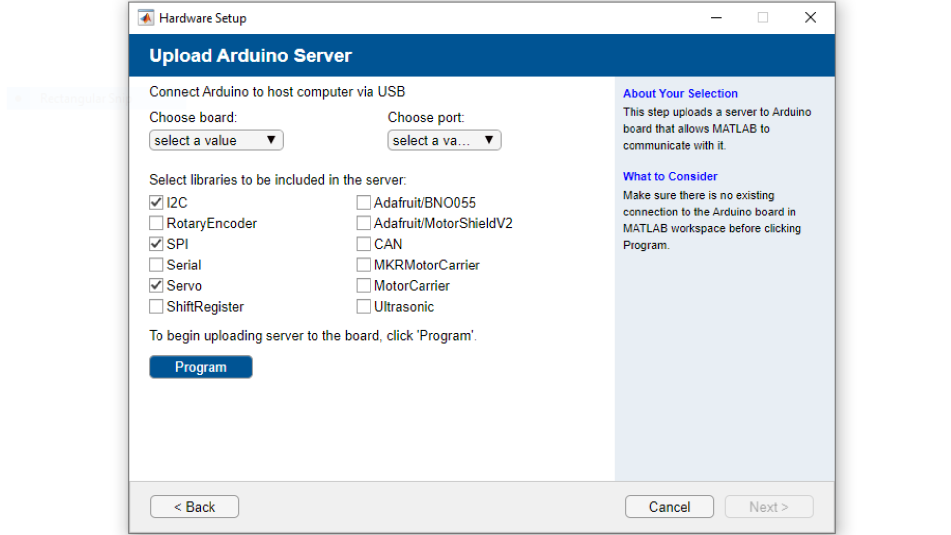
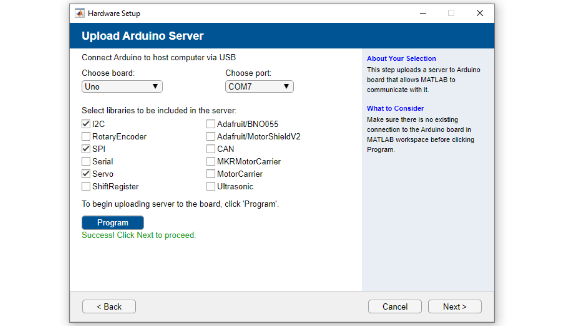
5. In this step you can review the connection type, Port, board and loaded libraries. You can also click on Test connection to evaluate the Arduino-MATLAB® connection. Next, you should see a Green check-mark signalling the successful connection, as shown in the image below.
6. The UNO R3 is now configured to interact with MATLAB®. Now to create the object in MATLAB®, we run the command
a = arduino()
7. Enter the command
writeDigitalPin(a, 'D13', 1);digitalWrite(D13, HIGH)aUnlike in the Arduino IDE, here you cannot address the built-in LED using the
macro.LED_BUILTIN
8. Now, you can use this command to continuously blink an LED as part of a
while1while (1)2 writeDigitalPin(a, 'D13', 0);3 pause(0.5);4 writeDigitalPin(a, 'D13', 1);5 pause(0.5);6endCircuit
On one breadboard there is a white jumper wire sending 5 volts to the potentiometer. The orange cable is connected to GND(Ground) and the gray wire is our input to A0. A0 will read the variable voltage coming in from pin13 after being adjusted through the potentiometer. On the right breadboard we have a simple LED circuit comprised of a red output wire from pin11, a resistor and the LED finally connected to GND via the green wire.

Make sure to connect the longer leg of the LED (anode) to the resistor and the shorter (cathode) to GND.
Programming the Board
1. Set your output to 1 in the previously mentioned way using
writeDigitalPin(a, 'D13', 1);readVoltage(a, 'A0');display(Volts)Volts1a = arduino();2writeDigitalPin(a, 'D13', 1)3while(1)4 Volts = readVoltage(a, 'A0');5 display(Volts);6 pause(0.5)7endThe amount assigned to
Volts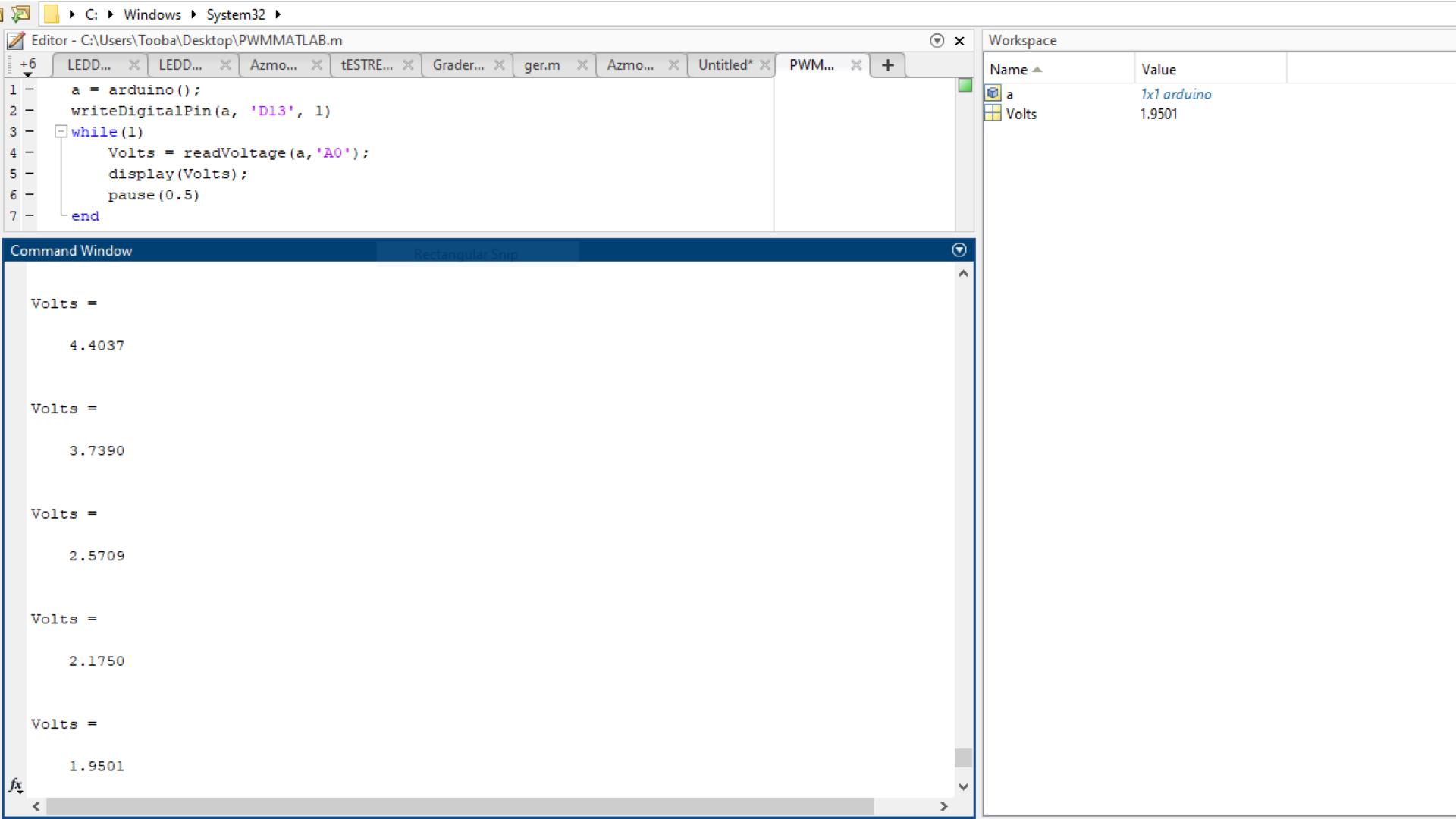
2. Set the value of
VoltswritePWMVoltage()1a = arduino();2writeDigitalPin(a, 'D13', 1)3while(1)4 Volts = readVoltage(a, 'A0');5 writePWMVoltage(a, 'D11', Volts)6 display(Volts);7 pause(0.5)8endTroubleshoot
- If the code gets frozen or seems to not be working try to clear previous Arduino objects linked to the device. You can do this by running the command
, for exampleclear <object>
will clear the Arduino object.clear a - If you get the message
ensure that you have installed the MATLAB® Support Package for Arduino Hardware.Unrecognized function or variable 'arduinosetup'
Conclusion
You can now control your output using variable inputs to control your devices and make use of the powerful features for scientific computing and developing engineering applications! Different input modulators similar to the potentiometer processed by the various toolboxes offered my MATLAB can lead to infinite types of output beyond that of the brightness of an LED.
Further Ideas
- You can also use the command line arguments to upload the MATLAB® server to the Arduino® UNO via the
command. See more information on using this function in the MathWorks® documentation.arduino() - Try writing a MATLAB® code that slowly increases and then decreases the blink speed instead of adjusting the brightness.
- Use different sensors and parts instead of the potentiometer and LED, for example a light sensor.